Call us now

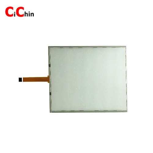

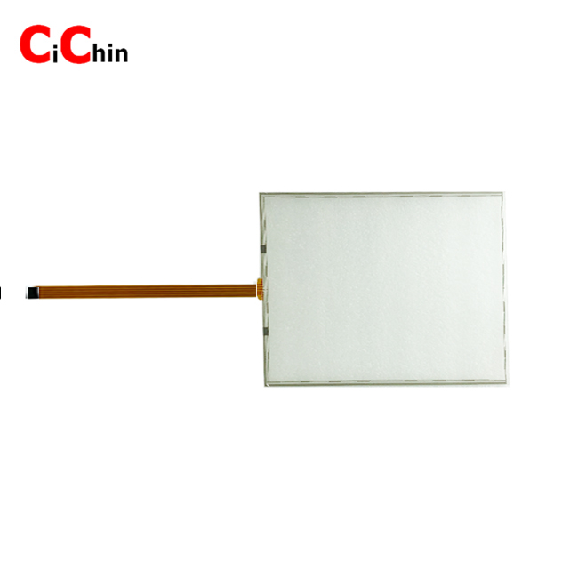


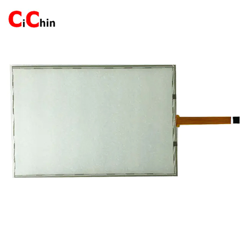
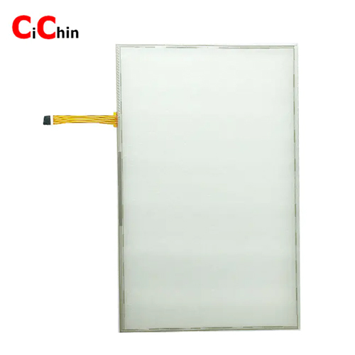
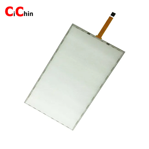
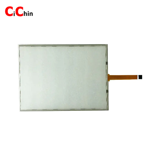
10.4 inch 5 wire resistive touch panel, accept customization
This is 5 wire resistive touch screen,widely used in below fields
Smart home, intercom systems
Outdoor equipments
Industrial monitors
Education and transportation
POS payment system
Banking and medical equipment
Measures and apparatus
Parameters:
| Size available | 5.6,7,8,8.4,9.7,10.1,10.4,10.7,11.6,12.1,14,15,15.6,17,17.3,18.5,19,21.5,22 inch 5 wire resistive touch screencustomize | ||
| Performance | |||
| Resoslution(Interpolation) | 4096*4096 | ||
| Linearity Error | <2.5% | ||
| Response Speed | <10ms | ||
| Mechanical | |||
| Input Method | Finger or stylus | ||
| Life Span | More than 10 million touches | ||
| Pressure | 10-100g | ||
| Surface Hardness | 3H | ||
| Optical | |||
| Light Transmission | >78% | ||
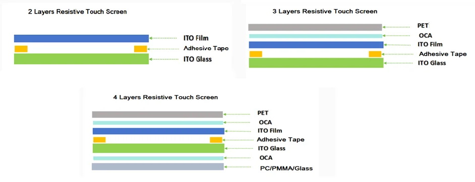
| Structure | |||
| 2 layers | Film+ITO glass | ||
| 3 layers | PET+Film+ITO glass (cusomize) | ||
| 4 layers | PET+Film+ITO glass+PC/PMMA/GLASS (customize) | ||
| Environmental | |||
| Operating Temperature | -10~ 50C | ||
| Storage Temperature | -20~ 60C | ||
| Operating Humidity | 0%~90% | ||
| Storage Humidity | 0% to 95% | ||
| Electrical | |||
| Voltage | Typical 3-7V | ||
| Current | 5mA~25mA | ||
| Interface | Full Duplex USB 2.0 (Full Speed) Plug and play compatible | ||
| Serial RS-232. Baud Rate: 9600, 8 Data Bits, 1 Stop Bit, No Parity | |||
| Isolation Resistance | >20M | ||
| Resistance | 300< X Axis <900, 200< Y Axis <800 (Varies with different size) | ||
| Agency Approvals | CE, Rohs | ||
| Operation System | Linux/ Dos / Windows /Mac/QNX | ||
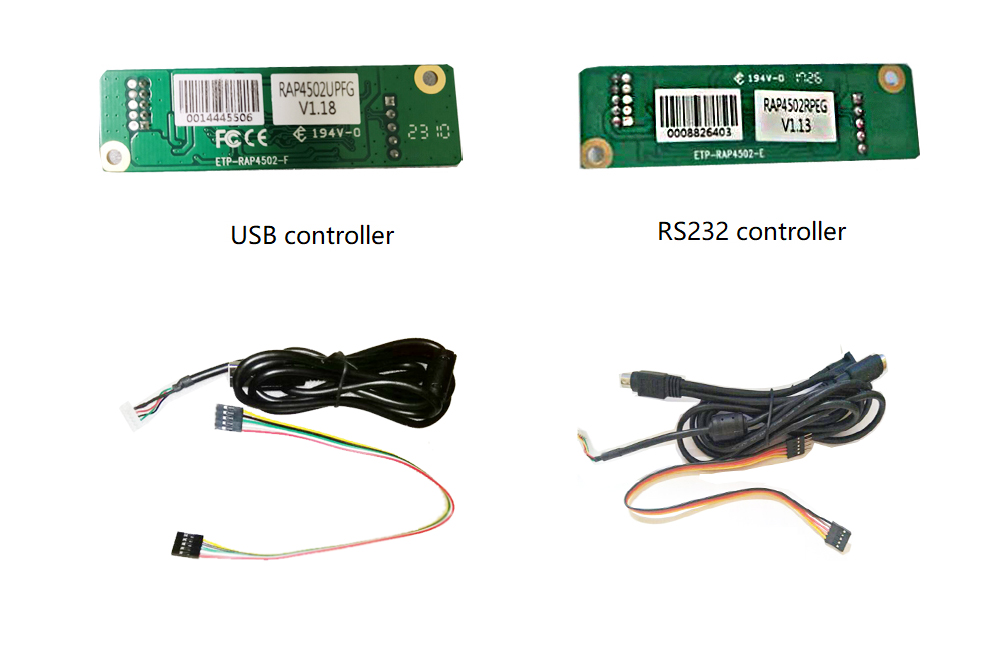
| Standard controller | EETI 5 wire/4 wire USB/RS232 controller kits(include board and calbes) | ||
| Special requirements | High-Transmittance Glass,light touch, Strengthened Glass,optional | ||
Available 5 wire resistive touch screen models:( if haven't found suitable one, please contact with us.)
| Size(inch) | Part no. | Outline Dimension | View Area | Active Area |
| 5.6 | TS056A5B001-A | 127.48X102.96 | 116.68X93.56 | 113.28X84.96 |
| 7 | TS070A5K002-A | 166.5X10⁴ | 154.6X93.64 | 152.4X91.44 |
| 8 | TS080A5B003-A | 182.6X140.8 | 168X127.2 | 164.8X123 |
| 8.4 | TS084A5B002-A | 187.00X147.00 | 175.50X133.00 | 171.88X129.16 |
| 9.7 | TS097A5B001 | 213.71X167.06 | 201.71X157.06 | 196.61X147.46 |
| 10.1 | TS101A5K001-A | 229.06X148.7 | 219.76X138.40 | 216.96X135.6 |
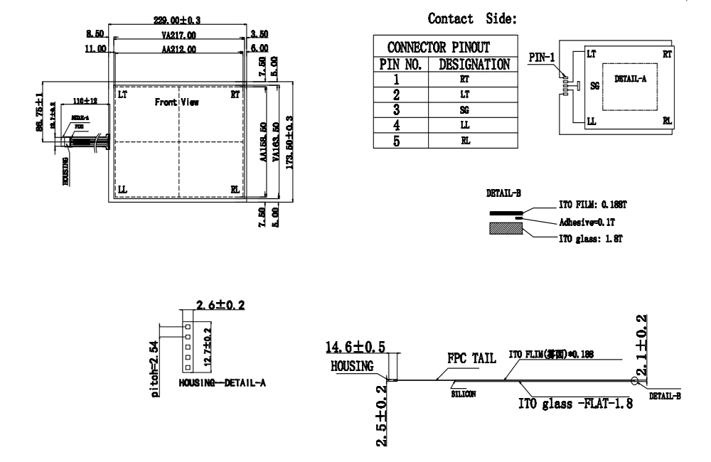
| 10.4 | TS104A5B001-A | 229X173.50 | 217X163.5 | 212.00X158.5 |
| 10.7 | TS107A5B001-A | 249.00X186.50 | 223.70X174.09 | 216.70X164.50 |
| 10.7 | TS107A5BP002-AA1 | 249.00X186.50 | 216.70X164.50 | 216.70X164.50 |
| 11.6 | TS116A5K001-AA1 | 268.00X158.6 | 258.00X148.00 | 256.00X144.0 |
| 12.1 | TS121A5B006-A | 266.0X203.0 | 191.6X254.2 | 186.0X248.0 |
| 12.1 | TS121A5B014-A | 261.8X199.8 | 250.05X189.3 | 246.8X185.5 |
| 14 | TS140A5B001 | 321.0X250.0 | 289.8X218.8 | 285.8X214.8 |
| 15 | TS150A5B009-A | 322.0X245.5 | 309.5X233.5 | 303.5X227.5 |
| 15 | TS150A5B009-B | 322.0X245.5 | 309.5X233.5 | 303.5X227.5 |
| 15.4 | TS154A5K004 | 361.8X227.6 | 336.1X214.2 | 331.8X207.6 |
| 15.6 | TS156A5K005-A | 359.3X209.5 | 345.56X194.99 | 344.16X193.59 |
| 15.6 | TS156A5K007-A | 363.8X215.9 | 346.83X196.14 | 344.83X194.14 |
| 17 | TS170A5B001-A | 355.0X288.0 | 341.5X277.0 | 337.0X269.00 |
| 17 | TS170A5B005-A | 356X286.5 | 343.0X275.5 | 337.0X269.5 |
| 17.3 | TS173A5K001-A | 401.0X234.0 | 386.0X219.0 | 383.0X216.0 |
| 18.5 | TS185A5K002-A | 429.37X253.6 | 418.8X237 | 409.79X230.4 |
| 19 | TS190A5B003-A | 396.0X323.0 | 381.0X310.6 | 375.0X300.0 |
| 19 | TS190A5B005-A | 393.4X316.65 | 380.9X305.65 | 377.3X302.05 |
| 19 | TS190A5K005-A | 426.6X272.10 | 414.2X261.1 | 411.2X257.3 |
| 21.5 | TS215A5K001-A | 494.0X290.0 | 481.84X273.31 | 475.5X267.3 |
| 22 | TS220A5KP002-AA1 | 488.0X310.0 | 475.0X298.0 | 471.0X294.0 |
How does the 5 wire resistive touch screen work?
The electrodes of a five-wire resistive touchscreen cannot be led out from four sides with conductive bars like those in a four-wire resistive touchscreen, as this would cause a short circuit. Instead, the electrodes are dispersed into numerous resistive patterns distributed around the periphery of the touchscreen and then led out from the four corners. The function of these patterns is to linearize the voltage gradient in the X and Y directions of the touchscreen, facilitating coordinate measurement. Working Principle: The controller applies a positive voltage to the upper layer, while the four lower leads are effectively grounded. When a finger touches the screen (TP), the upper layer is pressed into contact with the lower layer, allowing current to flow from the upper layer to the lower layer at the touch point. The current then exits through the four lower leads. The controller measures the four current values and uses a corresponding function to calculate the precise touch position through computation.
Sturcture
ITO FILM
Classification by Surface Treatment
a. Glossy Anti-Scratch Surface Low haze, providing better visual clarity. More challenging manufacturing process. Lower durability against scratches.
b. Glossy Anti-Newton Ring Surface Includes an anti-Newton ring layer. Reduces manufacturing difficulty.
c. Matte Anti-Glare Surface Features an anti-glare layer. Optimized for outdoor use with improved visibility.
Classification by Sheet Resistance
a. Low Resistance Primarily used in digital resistive touchscreens. Lower loop resistance, resulting in higher sensitivity.
b. High Resistance Mainly used in analog resistive touchscreens. Lighter etching traces, offering better visual appearance.
Classification by ITO Film Substrate
a. Single-Layer Film Uses a single-layer PET substrate, lower cost.
b. Double-Layer Film Uses a dual-layer composite PET substrate, higher cost. Softer and more durable, used in high-end products.
ITO GLASS
Classification by Strength
a. Chemically Strengthened Glass Treated with chemical tempering to increase surface compressive stress. Enhances overall strength but at a higher cost.
b. Standard Glass Conventional glass without special strengthening treatment
Classification by Transmittance
a. High-Transmittance Glass (AR-Coated) Features anti-reflective (AR) coating, improving light transmission by ~3% over standard glass.
b. Standard Glass No additional optical enhancement.
Classification by Thickness
Standard Thicknesses: 0.7mm / 1.1mm / 1.8mm
Special Thicknesses: 0.55mm / 2.8mm
Classification by Resistance
a. High Resistance (400) Used in analog resistive touchscreens.
b. Low Resistance Primarily for digital resistive touchscreens.
FPC
a. Core Materials of FPC: Base Material, Copper Foil, Stiffener, Coverlay
b. Common FPC Structures for Touchscreens
Touchscreens typically use either: Single-layer FPC/Double-layer FPC
c. FPC Material Specifications Base Material
Adhesive-based: Contains adhesive layer between copper and PI (polyimide).
Adhesive-less: Eliminates adhesive layer, consisting only of copper foil and PI (Thinner profile, Superior dimensional stability, Enhanced heat resistance, flex endurance, and chemical resistance, Now widely adopted in industry)
Copper Foil
Rolled Copper: Better flex endurance;Not suitable for ultra-thin boards or fine circuitry;Commonly used in resistive touch screens
Electrodeposited Copper: Preferred for capacitive touch screens
Stiffener Materials:
| Type | Characteristics | Application |
| PI | Low cost, prone to deformation | Resistive touchscreens |
| FR4 | Balanced cost/performance | Mid-range applications |
| Steel | High performance, expensive | Capacitive touchscreens |
PET COVER LENS
Thickness
| Thickness | Characteristics | Application |
| 0.125mm | Lighter touch force, poorer flatness | Niche applications requiring sensitive touch |
| 0.188mm | Balanced touch force and flatness | Standard for RTP (Resistive Touch Panels) |
| 0.25mm | Higher touch force, excellent flatness | Applications requiring durability |
Surface treatment
| Type | Characteristics | Key Parameters | Usage |
| Glossy Anti-Scratch | Scratch-resistant coating | High transmittance Low haze | Most common (indoor devices) |
| Matte Anti-Glare (AG) | Diffuse surface treatment | Reduced reflectivity Higher haze | Outdoor/sunlight-readable products |
| Glossy Anti-Newton Ring | Multi-layer optical construction | Eliminates Newton Ring | Limited use (3-layer" framed panels) |
Carrier Plate
Material
| Material | Characteristics |
| PC (Polycarbonate) | Impact-resistant, but lower surface hardness (max 2H), cost-effective |
| PMMA (Acrylic) | Impact-resistant, higher surface hardness (up to 3H), prone to warping/shrinkage |
| PC/PMMA Composite | Combines benefits of PC & PMMA, but higher cost |
| Glass | High surface hardness (6H), minimal warping/shrinkage, moderate cost, but less impact-resistant than plastics |
Thickness
Glass: 0.55mm / 0.7mm / 1.1mm / 1.8mm
PC/PMMA/Composite: 0.5mm / 0.65mm / 0.8mm / 1.0mm / 1.5mm
How to assemble the resistive touch screen to the housing?
To prevent false triggers, the housing must not directly contact the active touch area. Maintain an air gap of 0.20mm0.50mm between the housing and touchscreen surface. Recommendations for Customers: Step Design Add a peripheral step on the housing(Foam Tape) Width: Should not exceed TP silver trace boundaries Height: 0.20.5mm
When installing a resistive touch screen, it is recommended not to position the FPC downward. In outdoor environments with significant temperature differences, water vapor may condense on the touch screen surface. Additionally, external water, under the influence of gravity, may flow along the touch screen surface, seep through the casing, and reach the FPC bonding area. This can corrode the FPC bonding position and affect product reliability. If the touch screen is installed in this orientation, the waterproof performance of the entire device should be designed to a higher level.
Do resistive touchscreens require calibration?
A resistive touchscreen detects touch positions by measuring voltage signals generated at the contact point. When a finger or stylus presses the screen, the conductive layers (typically made of ITO) at the touched location undergo a change in resistance, producing corresponding voltage signals. These signals are then converted into X and Y coordinates, enabling precise touch recognition and positioning. From the operational principle described above, the key takeaway is that resistive touchscreens rely on voltage signal acquisition for coordinate recognition. The consistency of these voltage signals is fundamentally determined by the uniformity of the conductive layer (ITO layer). Industry-Specific Manufacturing Reality: ITO Layer Production: The industry-standard magnetron sputtering deposition process inherently creates thickness variations This results in sheet resistance (a conductivity equivalent) tolerances Typical industry specification: 400100 (representing ~25% variance) Performance Implications: Inter-panel voltage distribution variations are unavoidable due to: Initial sheet resistance tolerances Thickness non-uniformity (typically 5% across panel) Long-Term Performance Factors: ITO layer degradation characteristics: Annual sheet resistance drift: 3-8% (accelerated by environmental factors) Operational lifespan impact: 50,000+ touch cycles (industry benchmark) Compensation Solution: Dynamic calibration protocols are implemented to: Compensate for initial manufacturing variances Counteract progressive ITO aging effects Maintain 1% coordinate accuracy throughout product lifecycle In summary, to ensure touch accuracy, calibration is essential for resistive touchscreens.
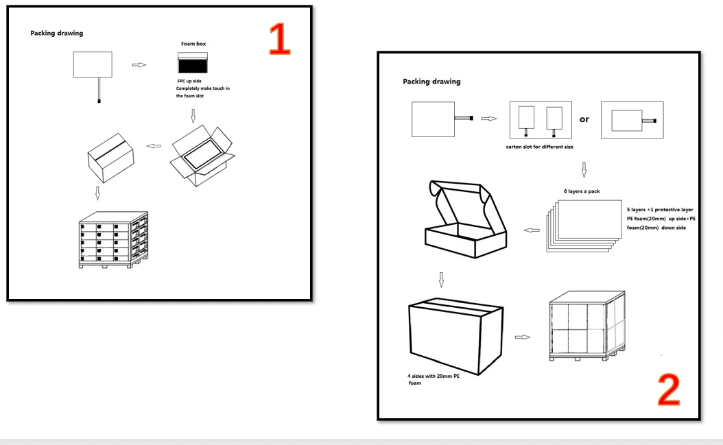
Package
Office
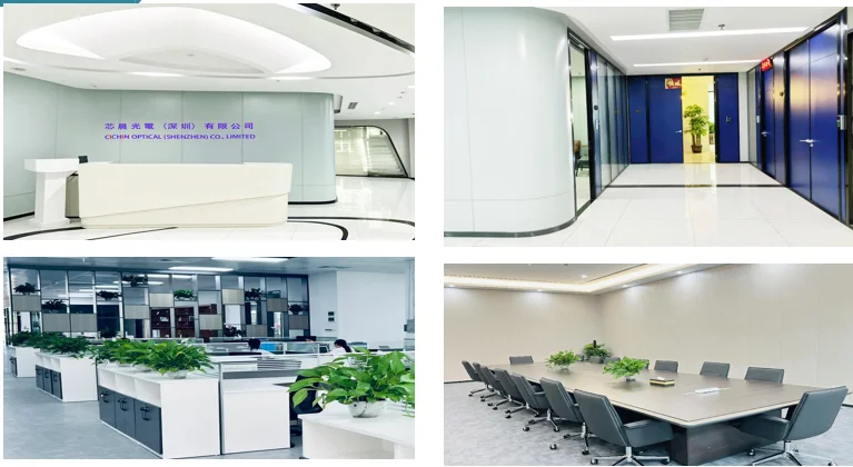
Factory


Price:


 Send Inquiry